4.2 Thermal noise
Thermal noise associated with the mirror masses and the last stage of their suspensions is likely to
be the most significant noise source at the low frequency end of the operating range of long
baseline gravitational wave detectors [85 ]. Above the operating range there are the internal
resonances of the test masses. The thermal noise in the operating range comes from the tails of these
resonant modes. For any simple harmonic oscillator such as a mass hung on a spring or hung
as a pendulum the spectral density of thermal motion of the mass can be expressed as [85]
where
]. Above the operating range there are the internal
resonances of the test masses. The thermal noise in the operating range comes from the tails of these
resonant modes. For any simple harmonic oscillator such as a mass hung on a spring or hung
as a pendulum the spectral density of thermal motion of the mass can be expressed as [85]
where  is Boltmann’s constant,
  is the temperature,
  is the mass and
  is the loss
angle or loss factor of the oscillator of angular resonant frequency
is the loss
angle or loss factor of the oscillator of angular resonant frequency  . This loss factor is the
phase lag angle between the displacement of the mass and any force applied to the mass at a
frequency well below
. This loss factor is the
phase lag angle between the displacement of the mass and any force applied to the mass at a
frequency well below  . In the case of a mass on a spring the loss factor is a measure of
the mechanical loss associated with the material of the spring. For a pendulum, most of the
energy is stored in the lossless gravitational field. Thus the loss factor is lower than that of the
material which is used for the wires or fibres used to suspend the pendulum. Indeed following
Saulson [85] it can be shown that for a pendulum of mass
. In the case of a mass on a spring the loss factor is a measure of
the mechanical loss associated with the material of the spring. For a pendulum, most of the
energy is stored in the lossless gravitational field. Thus the loss factor is lower than that of the
material which is used for the wires or fibres used to suspend the pendulum. Indeed following
Saulson [85] it can be shown that for a pendulum of mass  , suspended on four wires or fibres
of length
, suspended on four wires or fibres
of length  , the loss factor of the pendulum is related to the loss factor of the material by
where
, the loss factor of the pendulum is related to the loss factor of the material by
where  is the moment of the cross section of each wire, and
  is the tension in each wire whose
material has a Young’s modulus
is the tension in each wire whose
material has a Young’s modulus  . In general for most materials it appears that the intrinsic loss
factor is essentially independent of frequency over the range of interest for gravitational wave
detectors (although care has to be taken with some materials in that a form of damping known as
thermo-elastic damping can become important for wires of small cross-section [69] and for some
bulk crystalline materials [10]). In order to estimate the internal thermal noise of a test mass,
each resonant mode of the mass can be regarded as a harmonic oscillator. When the detector
operating range is well below the resonances of the masses, following Saulson [85], the effective
spectral density of thermal displacement of the front face of each mass can be expressed as:
In this formula
. In general for most materials it appears that the intrinsic loss
factor is essentially independent of frequency over the range of interest for gravitational wave
detectors (although care has to be taken with some materials in that a form of damping known as
thermo-elastic damping can become important for wires of small cross-section [69] and for some
bulk crystalline materials [10]). In order to estimate the internal thermal noise of a test mass,
each resonant mode of the mass can be regarded as a harmonic oscillator. When the detector
operating range is well below the resonances of the masses, following Saulson [85], the effective
spectral density of thermal displacement of the front face of each mass can be expressed as:
In this formula  is the mass of the test mass,
  is an angular frequency in the operating range of the
detector,
is an angular frequency in the operating range of the
detector,  is the resonant angular frequency of the fundamental mode,
  is the intrinsic
material loss, and
is the intrinsic
material loss, and  is a correction factor to include the effect of summation of the motion over the higher
order modes of the test mass (taking into account the effect of a finite optical beam size and correction for
the effective masses of the modes). Typically, as calculated by Gillespie and Raab [35],
is a correction factor to include the effect of summation of the motion over the higher
order modes of the test mass (taking into account the effect of a finite optical beam size and correction for
the effective masses of the modes). Typically, as calculated by Gillespie and Raab [35],  is a
number less than 10. A different and more general treatment of internal thermal noise using
evaluation of the relevant mechanical impedance has been carried out by Bondu et al. [8]. This was
based on work of Yuri Levin [55] and gives good agreement with the results of Gillespie and
Raab.
is a
number less than 10. A different and more general treatment of internal thermal noise using
evaluation of the relevant mechanical impedance has been carried out by Bondu et al. [8]. This was
based on work of Yuri Levin [55] and gives good agreement with the results of Gillespie and
Raab.
In order to keep thermal noise as low as possible the mechanical loss factors of the masses and pendulum
resonances should be as low as possible. Further the test masses must have a shape such that the
frequencies of the internal resonances are kept as high as possible, must be large enough to accommodate
the laser beam spot without excess diffraction losses, and must be massive enough to keep the
fluctuations due to radiation pressure at an acceptable level. Test masses range in mass from 6 kg
for GEO 600 to 30 kg for the first proposed upgrade to LIGO. To approach the best levels
of sensitivity discussed earlier the loss factors of the test masses must be  3 × 10⁻⁸ or
lower, and the loss factor of the pendulum resonances should be smaller than 10–10. Discussions
relevant to this are given in [78, 81]. Obtaining these values puts significant constraints on the
choice of material for the test masses and their suspending fibres. One viable solution which
should allow detector sensitivities to approach the level desired for upgraded detectors is to use
fused silica masses hung by fused silica fibres [12, 80], as the intrinsic loss factors in samples of
synthetic fused silica have been measured at around 3 × 10⁻⁸ [61, 93]. Still, the use of other
materials such as sapphire is being seriously considered for future detectors as mentioned in
Section 6 [11, 50, 78]. The technique of hydroxy-catalysis bonding provides a method of jointing oxide
materials in a suitably low loss way to allow ‘monolithic’ suspension systems to be constructed [79].
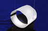
A picture of such a prototype fused silica mass suspended by two fused silica fibres, which
has been constructed in Glasgow and is being tested at the University of Perugia, is shown in
Figure 5.
3 × 10⁻⁸ or
lower, and the loss factor of the pendulum resonances should be smaller than 10–10. Discussions
relevant to this are given in [78, 81]. Obtaining these values puts significant constraints on the
choice of material for the test masses and their suspending fibres. One viable solution which
should allow detector sensitivities to approach the level desired for upgraded detectors is to use
fused silica masses hung by fused silica fibres [12, 80], as the intrinsic loss factors in samples of
synthetic fused silica have been measured at around 3 × 10⁻⁸ [61, 93]. Still, the use of other
materials such as sapphire is being seriously considered for future detectors as mentioned in
Section 6 [11, 50, 78]. The technique of hydroxy-catalysis bonding provides a method of jointing oxide
materials in a suitably low loss way to allow ‘monolithic’ suspension systems to be constructed [79].
A picture of such a prototype fused silica mass suspended by two fused silica fibres, which
has been constructed in Glasgow and is being tested at the University of Perugia, is shown in
Figure 5.